IH2VOF solves the 2DV Reynolds Averaged Navier–Stokes (RANS) equations at the clear fluid region and the Volume-Averaged Reynolds Averaged Navier–Stokes (VARANS) equations inside the porous media regions, based on the decomposition of the instantaneous velocity and pressure fields into mean and turbulent components, and the κ-ε equations for the turbulent kinetic energy κ, and its dissipation rate ε. This permits the simulation of any kind of coastal structure (e.g. rubble mound, vertical or mixed breakwaters). The free surface movement is tracked by the volume of fluid (VOF) method for one phase only, water and void.
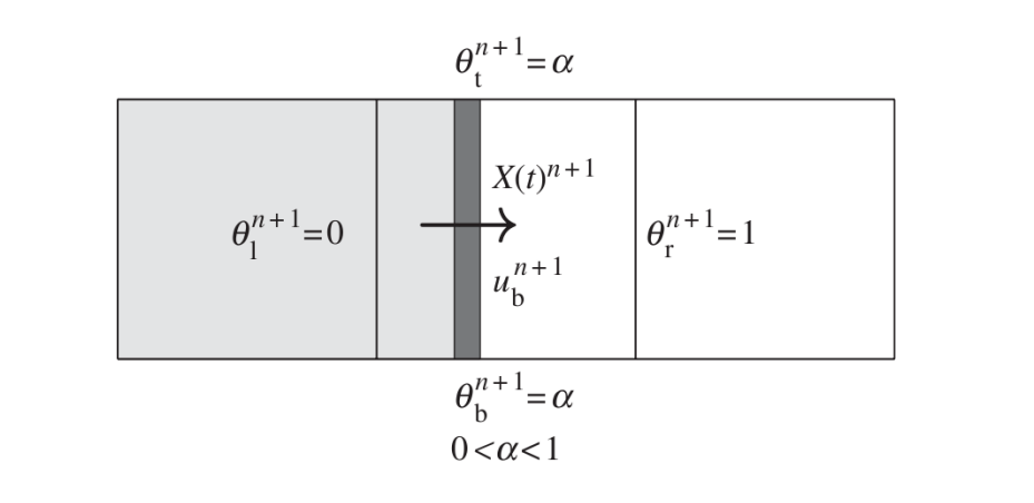
In order to replicate solid bodies immersed in the mesh, instead of treating them as sawtooth-shape, the model uses a cutting cell method first presented by Clarke et al. (1986). The main purpose of this technique is to use an orthogonal structured mesh in the simulations to save computational cost. This approach defines the openness function θ to define the fraction of volume of free space in the cell. According to this definition θ = 0 is a ’solid cell’ (entirely occupied by the solid), θ = 1 is a ’fluid cell’ and 0 < θ < 1 is a ’partial cell’. Variables in the cell or on the cell faces are redefined by the product of the openness coefficients times the original variables. To numerically implement this, partial cell coefficients need to be defined at both the cell centers and boundaries: θl , θr , θt , θb , which correspond to the openness at the left, right, top and bottom, respectively.
 IH2VOF includes a complete set of wave generation boundary conditions, which cover the vast majority of the range of relative water depths. These include a Dirichlet boundary condition and a moving boundary method, which are linked with an active wave absorption system to avoid an increase of the mean water level and the agitation. Also an internal source function can be used to generate waves, but it has to be linked with a dissipation zone. For further details see the Dirichlet Boundary Condition.
The RANS equations (clear fluid region) are redefined as follows:

The last term in the second equation is a virtual force. It appears because the IH2VOF model considers two different numerical techniques to simulate moving bodies within the computational domain. The first one is called ’virtual force method’ (see Mittal & Iaccarino 2005) and the other one is the ’direct forcing method’ (Mohd-Yusof 1997). This allows moving boundaries, which can be used to generate and absorb waves as piston wavemakers.
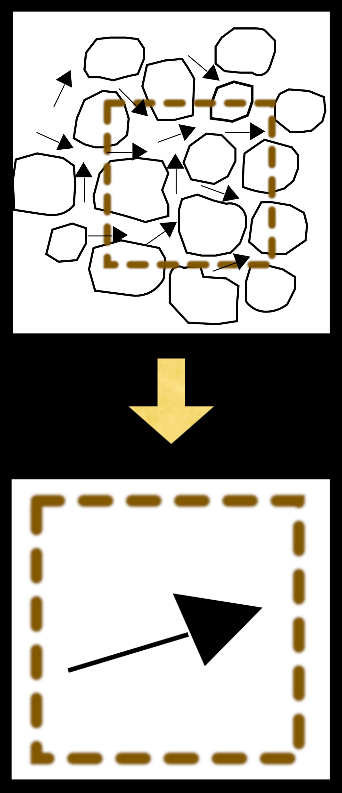
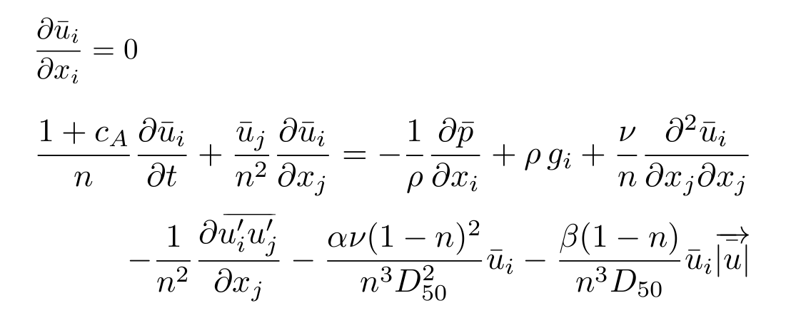
The flow inside the porous media is modeled by solving the VARANS equations, first presented by Hsu et al. (2002). These equations are derived by integrating the RANS equations over a control volume, and their final form is presented below:
The effects of the porous media are controlled by the porosity (n) and the mean size of the rocks (D50), and 3 friction coefficients (α, β and Ca). These have been thoroughly characterized for all kind of porous structures (berms, core…) and for porous beaches.
There are several ways of generating and absorbing waves in IH2VOF.
Dirichlet Boundary Condition
This fixed value boundary condition is the simplest and the first to be implemented in most wave generating models, since theories give analytical expressions for free surface and the velocity distribution throughout the water column.
As stated, to generate waves using this method, two variables for each time step are required. The first one is the free surface level at the generation boundary, which forces the model to set VOF function equals 1 below and 0 over it. Next, velocity (horizontal and vertical components), which is generated in advance at a chosen sampling rate and are then linearly interpolated by the model.
This kind of boundary condition can also be used to replicate the behaviour of any laboratory wave maker (at a resolution equal to cell size). In this case, the wave hydrodynamic produced by the wave maker displacement is neglected, which is consistent with first order generation methods. Active wave absorption has been built on top of it.
An example can be seen below, where waves are generated on the right boundary and absorbed on the left (moving) one.
Moving Boundary Method
The straightforward method to reproduce laboratory experiments is to replicate the action of a piston-type wave generator. This is done by simulating a solid object within the mesh which pushes the fluid when moving. Its movement is transferred into the model through the openness coefficients. Since the wave paddle position X(t) and velocity U (t) are provided as input, all the openness coefficients can be calculated for each time step.
The interaction of the solid with the fluid involves an additional term in the momentum equation. This body force, fb , represents the virtual boundary force, and it acts only on the solid boundary of the partial cells (0 < θ < 1).
This method works exactly like a Dirichlet boundary condition, but with several differences. First, velocity and free surface location are specified at different locations within the mesh according to the wave maker movement. Second, since a piston-type wave maker is replicated, only horizontal velocity is used. Since the paddle can move forwards and backwards, a larger mesh is needed in order to cover the area where the wave maker is expected to move.
This method also includes active wave absorption as defined in Schäffer & Klopman (2000), which modifies the velocity, and therefore, the displacement of the wave maker.
Internal Wave Maker
The internal wave generation method defines a mass source function in a specific region inside the computational domain. It always appears linked to the sponge layer, and was first developed to avoid wave re-reflection in the boundary where waves are generated.
The physical effect of the source region is the introduction of mass in the cells. Fluid is alternatively introduced or sucked into this region in order to generate wave crests and troughs. Different wave types (linear monochromatic waves, irregular waves, Stokes II and higher order, solitary waves and cnoidal waves) can be generated through the adequate definition of the source function, as presented in Lin & Liu (1999). Later on Lara et al. (2006) the method was generalized for random waves.
Since only one of the directions of the generated waves points towards the target area, the waves in the other direction ought to be absorbed in order to avoid their reflection on the boundary. This is done by means of a passive absorber, sponge layer. A collateral effect of this area is that the incident waves that return from the other direction are always absorbed.
Active wave absorption is included in the model, following the methodology developed by Schäffer & Klopman (2000). Although this method is based on shallow water linear theory, its performance is very good even if this condition is not fulfilled. It identifies the waves that reach a boundary and then absorbs them to avoid their reflection. The main advantage of this kind of absorption is that it prevents the energetic and mean water levels to increase unbounded, while adding no significant computational cost to the model.
This method also allows for an accurate wave generation simultaneously with the wave absorption for both the Dirichlet and the moving boundary conditions. The first step is to calculate the difference between the expected (target) free surface and the one measured in the model. Then the wave maker velocity is modified so as to generate the target wave and at the same time to cancel out the wave to be absorbed. Consequently, the correction of the velocity must be added to the target velocity of the generated wave. Finally if we are using the moving paddle another correction has to be applied to the position of the wave maker. The modified position is calculated by integrating the corrected velocity and adding it to the target displacement.
Active wave absorption can be applied alone on a boundary, to act like an open boundary condition for waves.
The video below shows wave generation on the right boundary, and active wave absorption on the left (moving) one.
The passive wave absorption method consists of a region in which a dissipation model is defined. This method was implemented to work together with the source function wave generation, and now that the other wave generation and active wave absorption methods are implemented as well it is less likely to be used. Its main goal is to avoid the reflections on the boundary, as waves generated by the source function travel in the two directions, but it also dissipates any other incident waves from the zone of interest.
This sponge layer is implemented following Israeli & Orszag (1981) formulation. The optimal length of this area is around 2 wave lengths, and allows the model to run for longer periods without the effect of inconvenient reflections. This region placed behind the source function area is an additional domain, hence the resultant mesh is significantly larger. This causes an even more expensive time cost.
IH2VOF can obtain the following fundamental variables in any cell of the mesh:
- VOF function (free surface)
- Velocity field (horizontal and vertical components)
- Pressure field
- Turbulent magnitudes: k and ε
Several derived magnitudes can be obtained out of the box, either directly or using the postprocessing GUI. Those magnitudes are related with the functionality and stability of coastal structures:
- Functionality:
- Free surface elevation along the whole domain
- Free surface gauges and spectra
- Run-up on a slope (breakwater or beach)
- Overtopping analysis: mean overtopping discharge, instantaneous overtopping discharge, instantaneous volume discharge, mean and instantaneous velocity during overtopping events and thickness of the overtopping mass of water.
- Transmitted energy leeward the structures by overtopping and throughout the porous media
- Stability:
- Time evolution of the pressure law around monolithic structures (crown-walls and vertical breakwaters)
- Time evolution of the forces (horizontal and uplift forces) and moments
- Time evolution of the safety factor coefficient
Additional magnitudes related with surf zone hydrodynamics can be also calculated:
- Gravity and infragravity wave evolution
- Wave breaking
- Undertow
- Bottom shear stress
IH2VOF is a mature model, however specific modules are currently under development to extent its capabilities:
- Interaction of the fluid with vegetation fields, considering either the average properties or the coupled movement of individual plants.


